This article introduces the Missing Weld anomaly type and highlights its usefulness in delta qual and AM production applications. The Missing Weld anomaly is only available in LAMQC Frozen Process.
LAMQC Frozen Process is tailored for additive manufacturing (AM) production environments where a “correct” or “qualified build” can be defined.
We will examine components from two different builds and highlight how the Missing Weld anomaly type calls attention to anomalies that LAMQC can not detect.
Welded Region contains missing corner in LAMQC
Missing Weld anomaly type in LAMQC Frozen Process
LAMQC:
Calibration Block
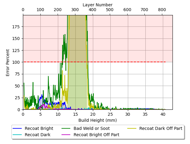
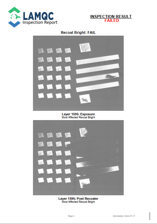
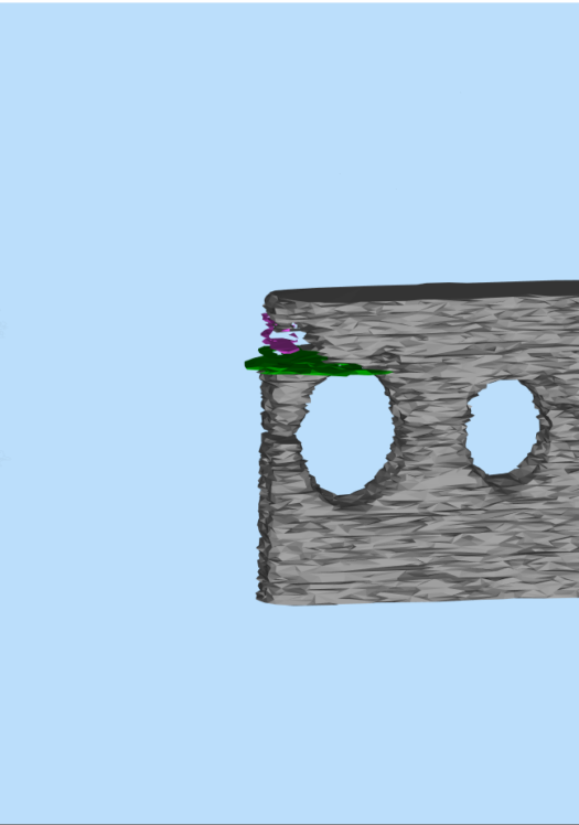
This calibration block has both Bad Weld or Soot (green) and Bright Recoat Off Part (purple) anomalies. The most striking part of this calibration block is the section of missing weld at the top left corner.
LAMQC does not see the region of missing weld as an anomaly and an operator or qualification team could easily overlook this issue.
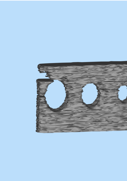
LAMQC: Weld (grey)
Missing Weld is not an anomaly type
LAMQC Frozen Process:
Calibration Block
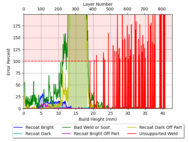
LAMQC Frozen Process addresses limitations of LAMQC with the Missing Weld anomaly type by requiring the a “correct” or “qualified” build.
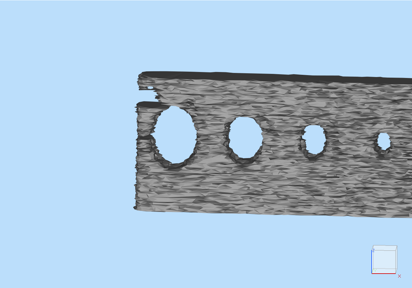
The weld solid model for the “correct” calibration block includes the upper left corner as shown on the left image.
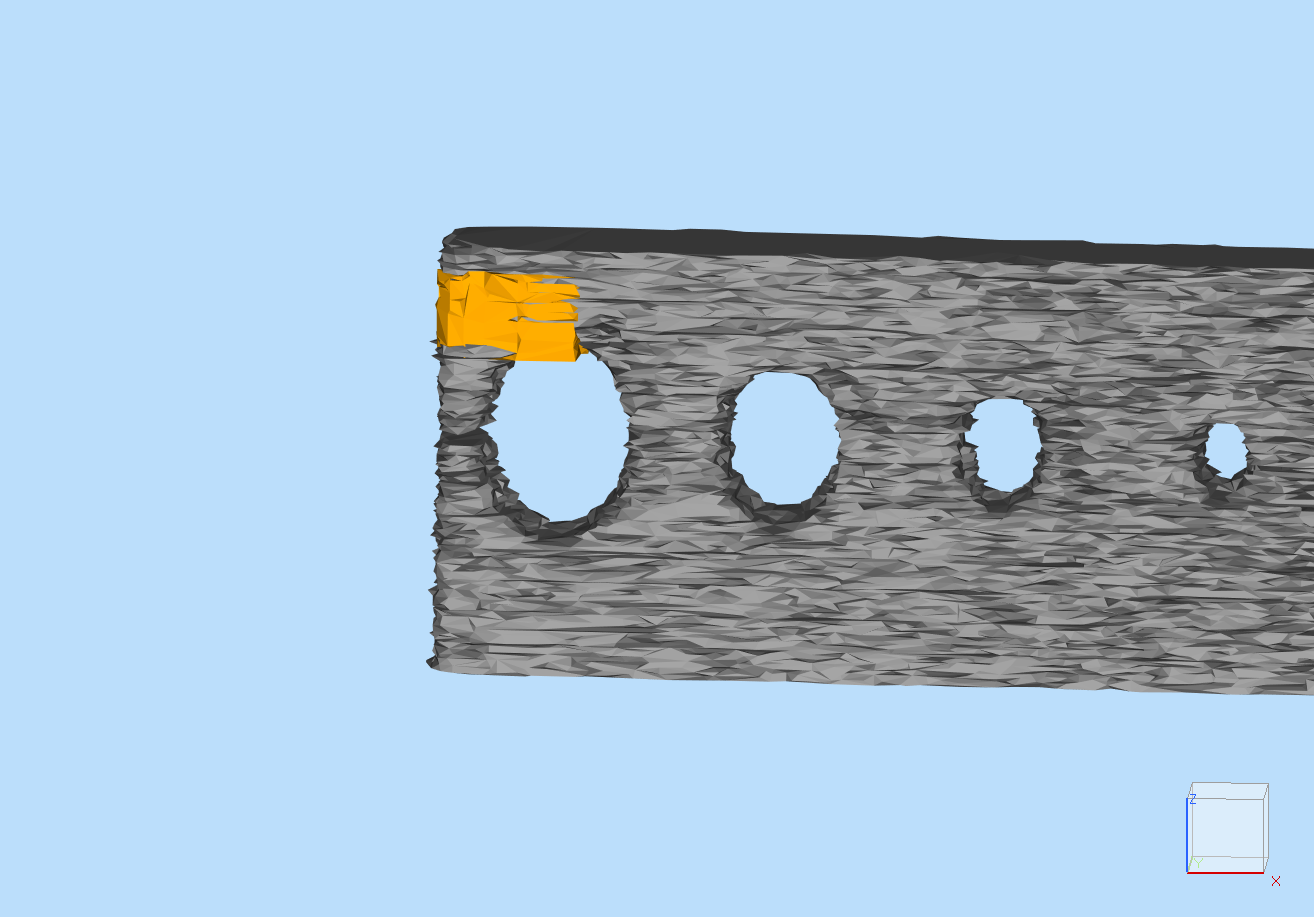
The image on the right illustrates the orange Missing Weld anomaly from the “current” build superimposed on the “correct” weld.
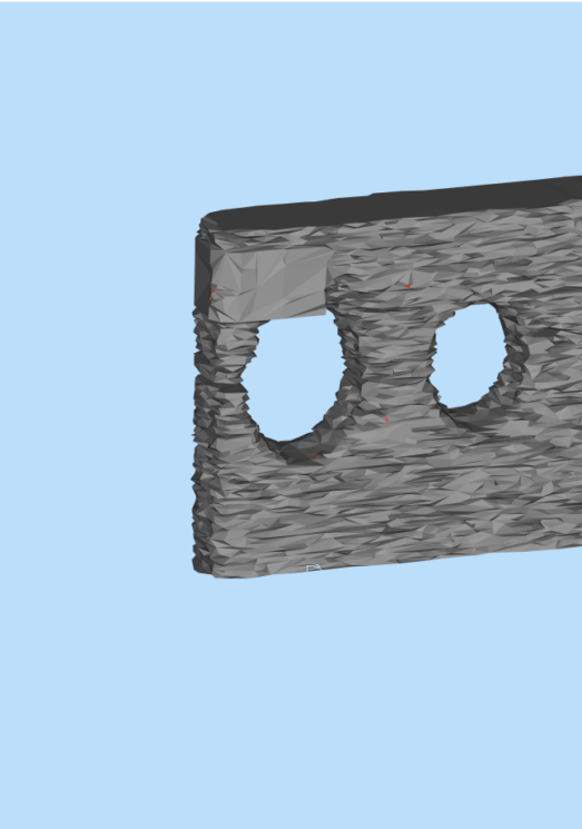
Frozen Process: Weld (grey)
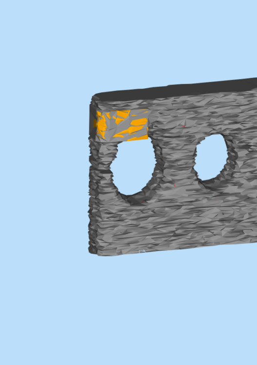
Frozen Process: Missing Weld (orange)
LAMQC:
Turbine Blade
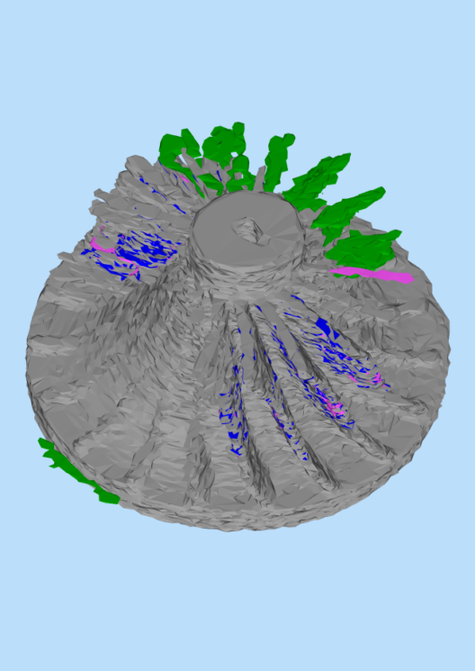
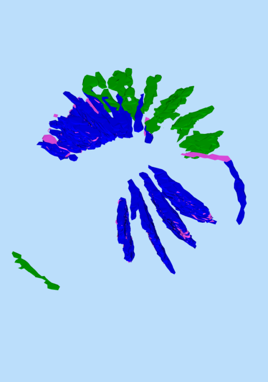
This turbine blade tip-shroud has Recoat Dark (teal) and Recoat Bright (blue) anomalies as shown in the right image. These anomalies often negatively impact part quality.
Unlike the calibration block example, the missing weld in the turbine blade tip-cap is difficult to see in LAMQC, increasing the risk that an operator or quality team may overlook the problem.
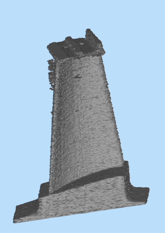
LAMQC: Weld (grey)
Anomalies interior to weld

Recoat Dark and Recoat Bright anomalies at the tip shroud.
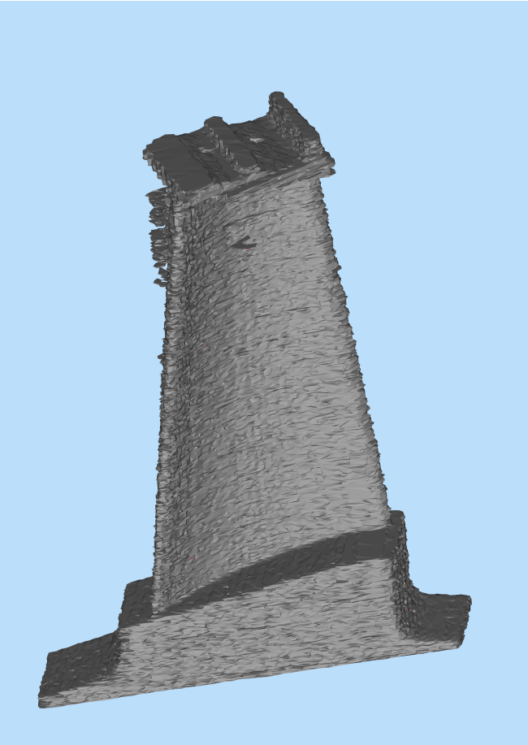
LAMQC Frozen Process:
Turbine Blade
The Missing Weld anomaly type (right) allow easy identification of regions that lack weld. Missing Weld regions often have severely debited tensile and LCF and the surfaces often don’t clean up in machining, making the Missing Weld anomaly critical for delta quals and new machine certification.
If the AM Purchaser has stringent requirements, the part should be scrapped or be submitted on SDR (Supplier Deviation Request), NCN (Non-Conformance Notification) or for Engineering Review Board approval.
If AM Purchaser review process does not scrap the part, it should be dispositioned for tip-shroud inspection to determine the severity of the anomaly.
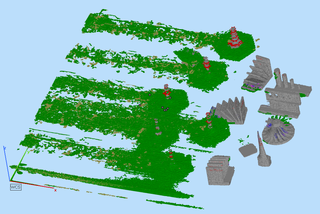
Unknown Part: All Anomalies
Non-continuous weld visible.

Bad Weld or Soot (green) removed.
Non-continuous weld visible.